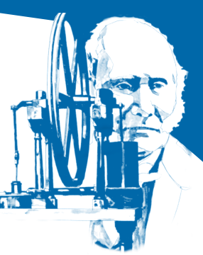
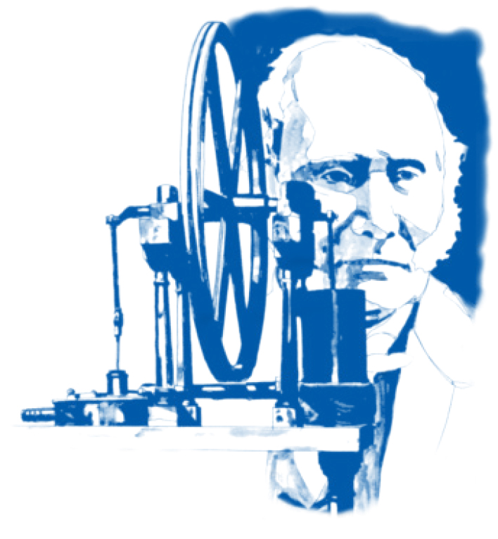
The Stirling cycle is a thermodynamic closed cycle invented in 1816 by the Scottish minister Robert Stirling. It was used as an engine and was considered at the time to be capable of replacing the steam engine since steam boilers were prone to life-threatening explosions. The counterpart of the Stirling engine, the refrigerator, was first recognized in 1832. Both machines experienced highs and lows during the nineteenth century. The principle behind the machines was almost condemned to obscurity after the invention of the internal combustion engine (gas-, petrol-, and diesel motors) and compressor refrigerators with external evaporation.
In 1938 the famous Dutch Philips Research Laboratory was looking for a means to power electricity generators for short wave communication systems in remote areas without electricity supply. The practically-forgotten Stirling engine attracted their attention.
In 1946 Philips started optimizing the Stirling cycle to be used for cryogenic cooling. The result was the development of the world conquering Stirling Cryogenerator, marking the start of significant cryogenic activities at Philips. Though the Stirling engine itself never became a commercial success, the Stirling Cryogenerator has been selling by thousands worldwide and has been incorporated in equipment and projects used from Antarctica to the North Pole.
Stirling efficiency
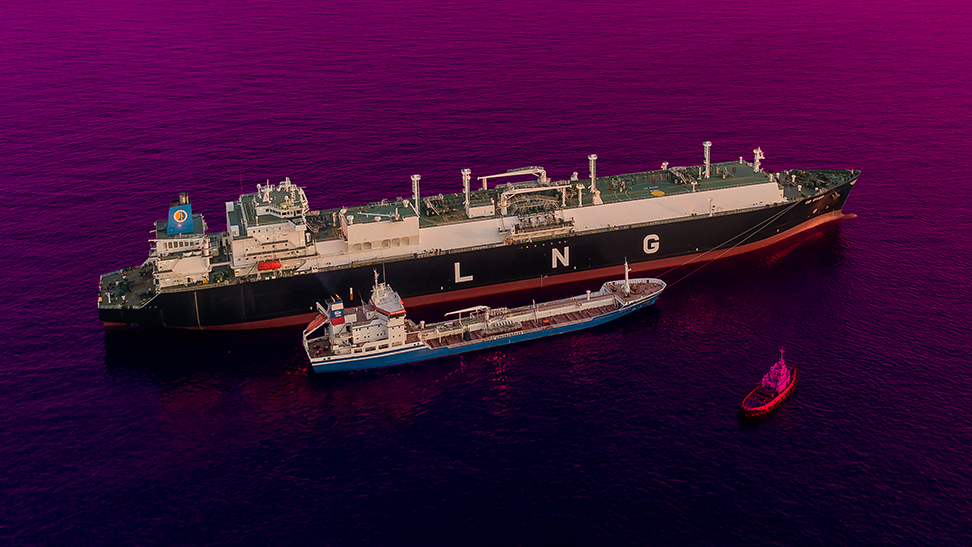
The Stirling Cryogenerator is extremely efficient compared to other cryogenic cooling cycles. Carnot efficiency is 30% at 77K, resulting in a high practical over-all efficiency defined as Watts of cooling power available to the application divided by kW of electric input power. Depending the application’s temperature, the over-all efficiency of the Stirling Cryogenerator varies between 10% for LN2 applications to over 20% for LNG systems.
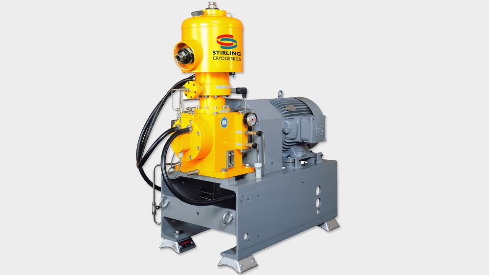
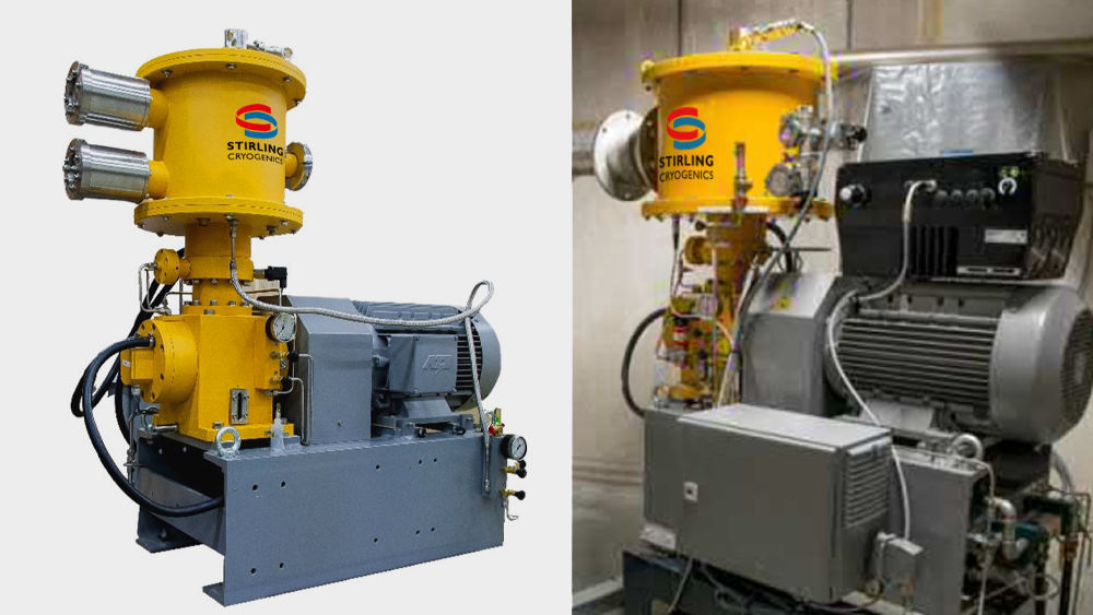
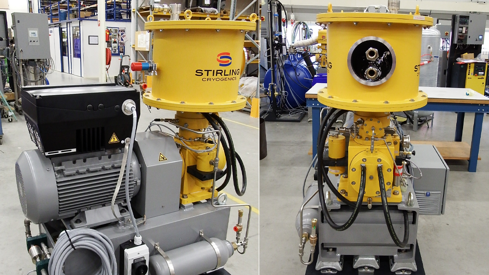
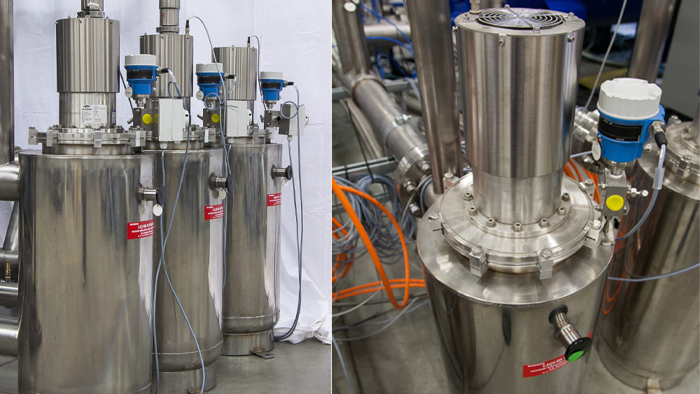
The Stirling Cryogenerator
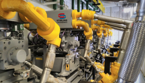
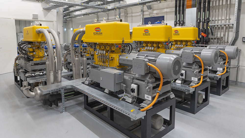
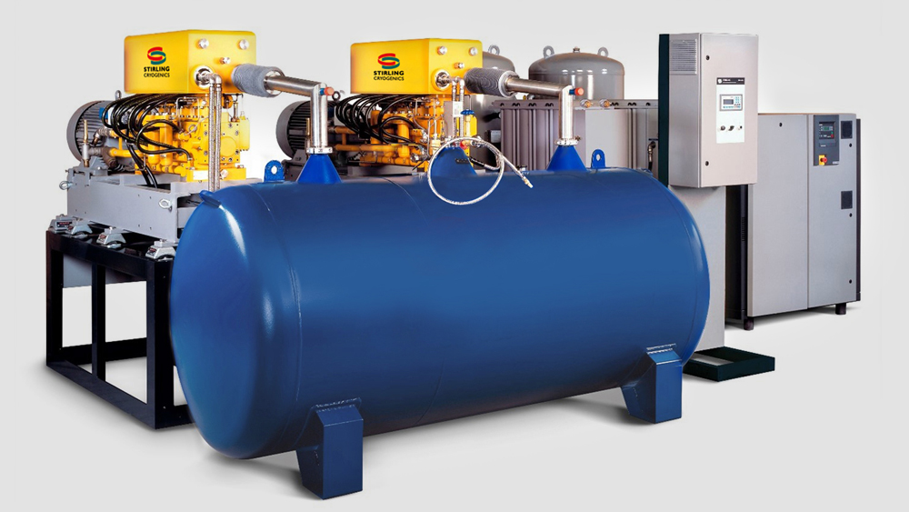
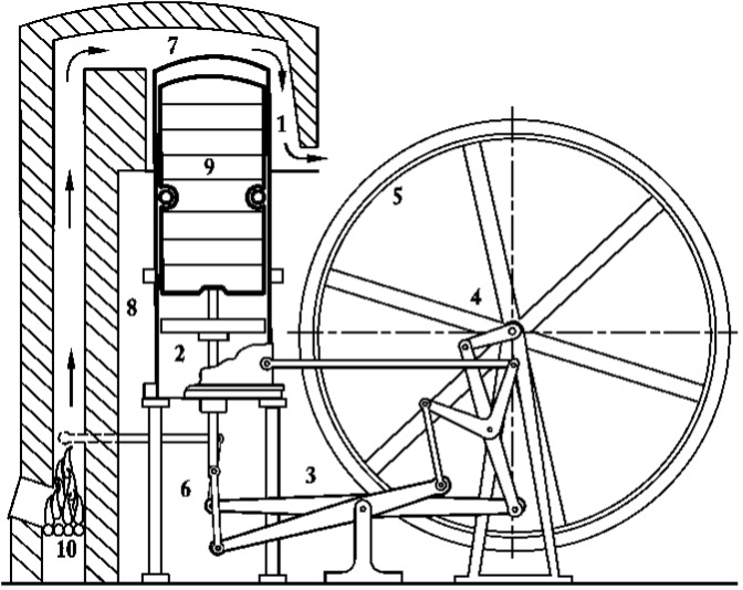
The central element in all equipment of Stirling Cryogenics is the Stirling Cycle Cryogenerator. The Stirling Cycle is remarkable because it is a closed cycle in which the Cryogenerator’s internal working gas (He) never comes into contact with the fluid to be cooled; they connect only by flow of heat through the heat-exchanger wall. This concept eliminates contamination of the customers process as well as of the Stirling Cycle working gas, resulting in long continuous operating periods and longevity.
The Stirling Cycle alternately compresses and expands a fixed quantity of helium in a closed cycle. The compression takes place at room temperature to facilitate the discharge of heat caused by compression, whereas the expansion is performed at the cryogenic temperature required by the application
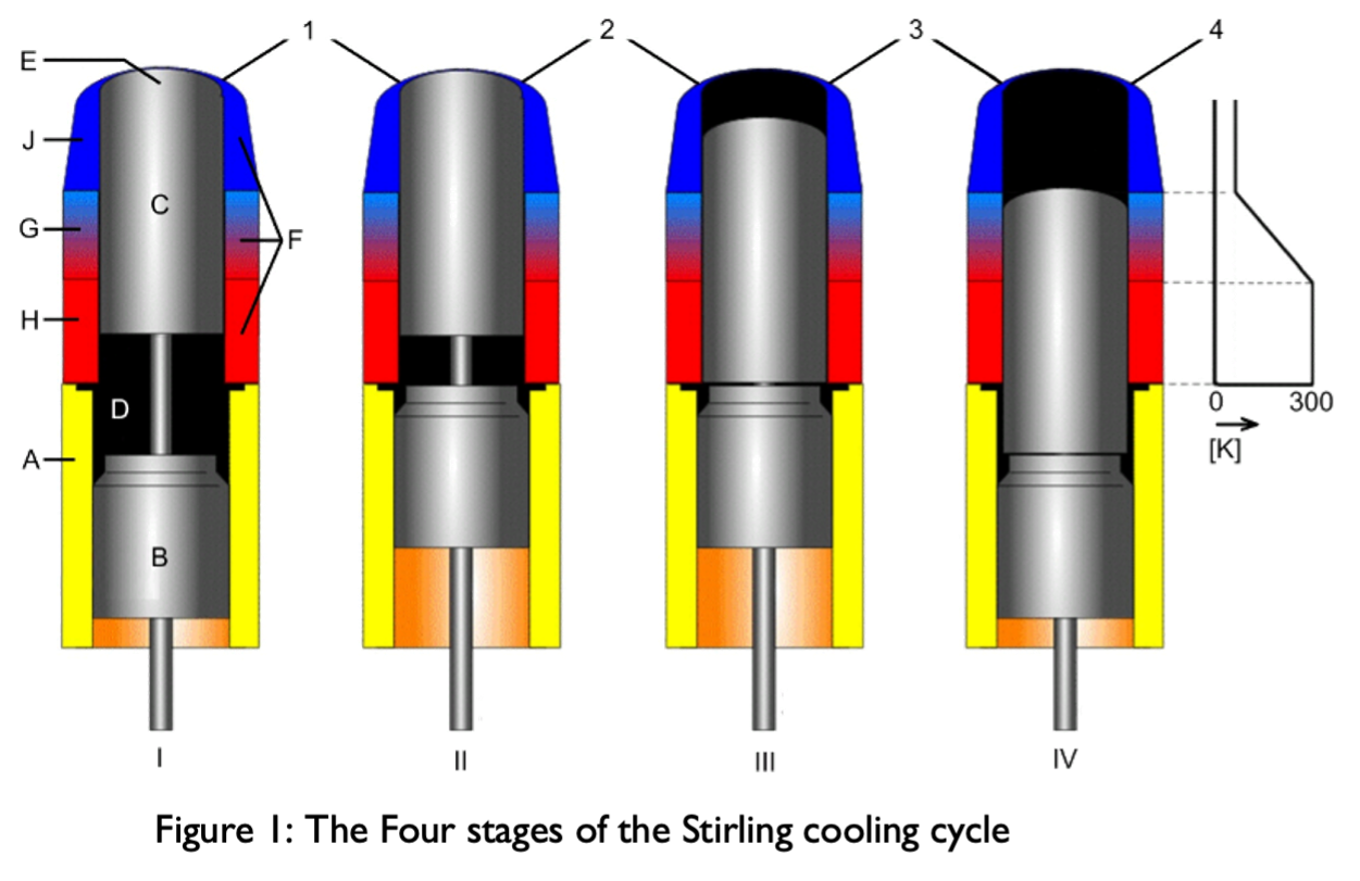
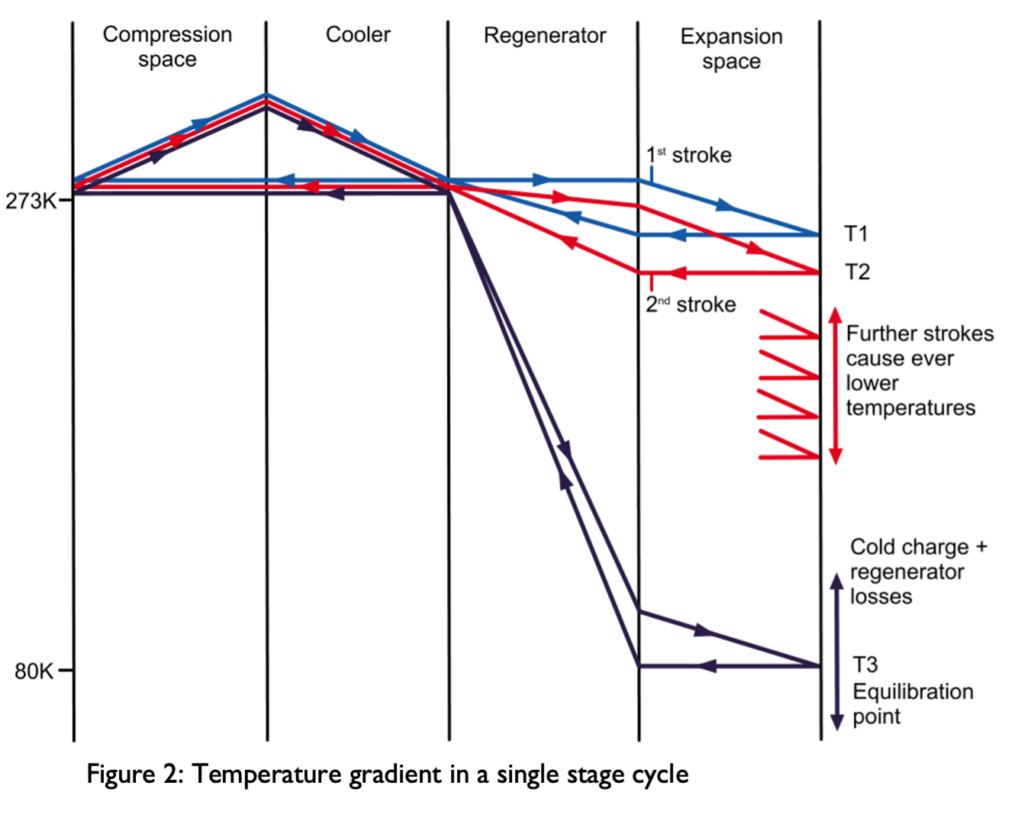
For the purpose of explanation, the process may be split up into four distinct piston positions illustrated in Figure 1. In position I, all helium is at room temperature in space D. Going to position II, this gas is compressed by piston B increasing the gas temperature to about 80°C, refer to Figure 2, column 1. When the displacer C moves down from position II to III, the gas is displaced from space D to space E, forcing it first through the cooler H where the compression heat is dissipated into the cooling water, reducing the gas temperature to about 15°C (column 2). Next, the helium flows through regenerator G. Using the cold which was stored in the regenerator by the previous cycle, the helium gas is cooled to almost the final working temperature when arriving in space E (column 3). The final and main action is the displacer and piston moving down to position IV, expanding the helium gas. This expansion creates the actual cooling power in the cold heat exchanger J (column 4), cooling the customers process.
For a new cycle to begin, the displacer moves up to position I, displacing the helium to space D again. The regenerator is cooled by the passing helium (column 3), storing cold to be used in the next cycle. The helium is reheated to nearly room temperature so the initial situation of the cycle has now been restored for the cycle to repeat. This cycle is typically repeated at 25 Hz, providing a continuous extraction of heat.
When starting warm, the Cryogenerator will initially first cool down itself, building up a cold buffer in the regenerator (column 3). This cool-down requires about 10 minutes only, allowing a fast start-up of the total process.


 For a new cycle to begin, the displacer moves up to position I, displacing the helium to space D again. The regenerator is cooled by the passing helium (column 3), storing cold to be used in the next cycle. The helium is reheated to nearly room temperature so the initial situation of the cycle has now been restored for the cycle to repeat. This cycle is typically repeated at 25 Hz, providing a continuous extraction of heat.